General description:
Operation:
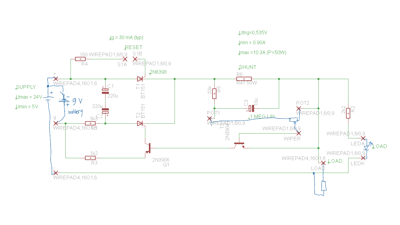
Electronic fuse is intended to be used in fault- diagnosis purposes for DC- circuits, for example when examining cause for a fuse to blow, with 5A current draw or less. Supply voltage can range from 5 to 24 volts. Fuse is connected to the high side, i.e in the positive lead of the circuit under test. Negative terminal shall be connected to circuit ground point. Swithching on the device connects 9V internal battery across C1 & C2, through 3k3 resistor, charging them so that C2 lower end becomes positive. The cutoff current is first set by the potentiometer scale. supply voltage and load connceted, pressing reset button will turn on SCR T1 (2N6398) and current starts flowing. A LED indicates this. If current remais below the set limit, voltage drop cross shunt resistor R6 is not sufficient to turn on transistor T3. R5 and C3 provide a filter for switchoff.
If current exceeds the limit, transistor T3 turns on, causing PNP-transistor Q1 to conduct and trigger commutation SCR T2 (2N6398), which discharges C1 and C2 through T1 causing load current flow opposite to load current, causing it to drop below hold current and T1 to turn off. To reset, push the reset button again. Polarity across C1 and C2 varies, so a non-polarized cap or two polarized electrolytics back-to back can be used.
Circuit is sensitive to SCR's properties and is tested with semiconductor types indicated. other SCR's can be used, but trigger circuit resistors may have to be altered.
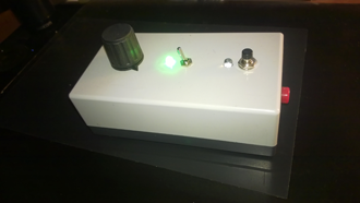
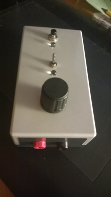
Hardware:
Software: None
Documents:
Connection diagram